-
There is no denying that it is very convenient for the public to use the wireless network, which is more and more popularly used in recent years. However, if the high speed and efficiency are required, the wired network must be more suitable for you to choose, which always works with Ethernet patch cables to enable a more secure network with faster speed. In general, except for some special devices like cellphone that can only used in the wireless network, the rest of your devices will perform better in the wired network.

Would you also like to deploy a wired network for your home? Since the deployment of a wired network is more sophisticated than that of a wireless network, this paper will present some considerations for you to set up a fast and smooth wired home network.
Design Your Network
Before deploying the wired network, there are some points that you should take into account. Firstly, you must decide how many rooms you want to run your wired network through, which will mainly determine the deploying budget. Because it will dictate how many feet of Ethernet patch cable you need to use. Secondly, you must confirm how many devices you would like to connect to the network and where you decide to locate them. Thirdly, since there may be a lot of Ethernet patch cables put in use in the wired network deployment, the wire distribution also becomes very crucial for a neat and smooth wired network which you should attach importance to. Considering that these Ethernet cables would be easy to mess up, you’d better to design the wired network and consider all possible problems that may occur during the installation.
Besides, there are two notes that you should also pay attention to when designing the network. The one is not to place the Ethernet patch cables near the devices, for instance, microwave and TV, which will have a negative effect on the performance of data transmission. Another one is to put the router in a central place of your network, ensuring good signals when your network runs.
Choose One Type of Patch Cable
As we all know, choosing a proper patch cable is extremely important that can make a great difference to the network speed. If you want to gain a stable network with high data transmission rate, then you should choose the most suitable cable for your network. At present, the patch cables used for the wired networks are usually Ethernet patch cables, which can be divided into various types, such as, Cat 5, Cat 5e, Cat 6, Cat 6a, Cat 7 patch cable, etc. Among these types, Cat 5e and Cat 6a patch cable are more commonly used the wired network in recent years, both of which are highly recommended as the cost effective solutions.
Prepare the Related Materials and Tools
After making the decisions about where and how the cables will be distributed, you should firstly measure the distances of the connections in your network and calculate how long the Ethernet patch cable the whole connection needs, as the Ethernet patch cable is the main equipment in the network. To avoid some unexpected issues, the whole length of the Ethernet patch cable you prepare should slightly longer than the calculated length. In addition, there are many other tools you should also prepare before the installation, for example, wall plates, jack ports, drywall cutters, cable clips, etc. All these tools will be used in the installing process. Hence, you should check and confirm the preparation, so that the installation procedures will be smoothly processed as planed.
Conclusion
There is no doubt that the wired network performs higher than the wireless network, although the deployment of the wired network is much more sophisticated. If you want to own a more secure and faster network, then the wired network would be a better choice for you and the points mentioned above are three important factors that would be useful for you to make a fast deployment for the smooth wired home network.
 votre commentaire
-
Patch Panel Overview
The patch panel, also known as the patch bay, patch field or jack field, is a functional unit with a number of same or similar jacks, designed to conveniently and flexibly connect, disconnect and monitor circuits in the cabling network. There is no doubt that the patch panel plays an important role in collecting data and routing it to the intended destination, with the function of enabling the ease of cabling network management and avoiding the data transmission error or failure.
At present, there are both copper and fiber patch panels available on the market, both of which are very popularly used due to their features and advantages. To better know about the patch panel, here offers a kind of 48 port cat6 patch panel in the following figure. From this figure, you can easily learn the appearance of the front and rear of the 48 port cat6 patch panel.

Patch Panel Importance to Cabling Network
We used to regard the patch panel as the “traffic light” for our cabling network. Is there any evidence to support this statement? In fact, we can’t deny that no matter how large or small the patch panel is, it is always the crucial element in our cabling network that has the ability to terminate cable elements and transmit the signal to the final destination. Moreover, using the patch panel can better install and manage the multiple cables in our cabling network, for an easier cabling management.
With the mentioned above advantages and constantly improved functions, the patch panel becomes more and more commonly used in computer networking, recording studios, radio, television, etc. Since it is so important to our system, we should ensure that there is no problem with the patch panel before our system runs. Because if there is something wrong with the patch panel, the data would be transmitted wrongly or unsuccessfully.
Selecting a Suitable Patch Panel for Your Cabling Network
As the patch panel is so crucial in the administration of the telecommunications network, it is highly recommended to select a proper patch panel for better cabling management. Since there are both copper and fiber patch panel available on the market, let’s discuss the advantages and disadvantages of the two kinds of the patch panels and select one type which is the most suitable for our system.
It is well known that the patch panel can be part of networks with either fiber or copper cabling. As fiber can transmit the signals faster than copper, does it mean that fiber patch panel performs better than copper patch panel in the cabling network? The answer is no. Why? Because all the patch panels are subject to the same standards that provide signal and speed performance ratings for other network components, no matter which materials the patch panels are made up of. Meanwhile, the patch panel is primarily used for directing signal traffic rather than move signal at a required speed. Hence, the materials of the patch panels do make little difference in the cabling performance. As for the manufacturing cost, fiber patch panel is much expensive than copper patch panel that can be up to 40 percent higher. In short, copper patch panel is really a good choice for cabling network if the three factors mentioned above is considered.
Is there any advantage if we choose the fiber patch panel for our cabling network? Of course. The fiber patch panel has only two ports and doesn’t require the hardwiring, which is much easier to install than the copper patch panel. After all, each pair of the wires should have a port if you choose the copper patch panel, which may take more time to install.
Conclusion
The patch panel is the “traffic light” in cabling network which allows for terminating long and troublesome cables, enabling the signals to be transmitted directly through a patch code to its destination. Although there are both copper and fiber patch panel available on the market, the copper patch panel is highly recommended as an cost effective solution. Do you consider owning one copper patch panel at hand? You can simply get it from FS.COM that offers 24 port cat5 patch panel, 48 port cat5 patch panel, 24 port cat6 patch panel and 48 port cat6 patch panel.
votre commentaire
-
Are the Ethernet patch cables you purchase from the local or online stores always at the proper length? Or not so suitable for your network because they are too long or too short that don’t meet your expectations? Have you ever considered making the improper Ethernet patch cable into a suitable one by yourself, so that you can deploy your network by using you own Ethernet patch cable and save a lot of money, time and space? In fact, terminating the Ethernet patch cables is not so difficult but very useful for fast network deployment, which will be presented in the post. Meanwhile, there are several important things you should take into consideration before making the Ethernet patch cable termination, which will be also illustrated in details. Hope these information will guide you to make your own Ethernet patch cable and then deploy your Ethernet network in a very fast, smooth and cost effective manner.
Selecting a Proper Ethernet Patch CableBefore making the Ethernet patch cable termination, you should choose one kind of Ethernet patch cable which is most suitable for your network, since there are various kinds of Ethernet patch cables available on the market, such as, cat5, cat5e, cat6, cat6a, cat7, etc. Considering that cat5e, cat6 and cat7 patch cable are the most commonly used ones at present, both of which will be introduced the following text.
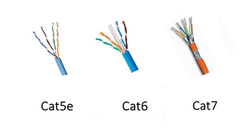
As an upgrade version of cat5 patch cable, cat5e patch cable has the ability to support gigabit speed, allowing for a faster, more reliable and steady network. It is much commonly used in home and office applications. As for cat6 patch cable, it is an enhanced version of cat5e patch cable that has much more sophisticated structure, as shown in the above figure. It is an ideal solution to face future-proof network that supports the transmission speed up to 10 gigabit with a long transmission distance. In contrast to cat5e and cat6 patch cable, cat7 patch cable is a kind of shielded Ethernet cable that has a great improvement in the capacity and reliability. It is more expensive since it has been the most durable and longer-lifespan Ethernet patch cable at present. As for the structural differences among cat5e, cat6 and cat7 patch cable, it is very easy to learn from the above figure.
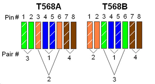
Choosing a Proper Wiring SchemeIn general, there are two common wiring schemes, T568A and T568B, which are designed to specify the arrangement of the colored wires for terminating the Ethernet patch cable. That’s to say, if you want to terminate your cable, you should arrange the colored wires in a correct order according to the standard of T568A or T568B, as shown in the following figure. As for their applications, T568A is always applied in home-networking connections, while T568B is strongly suggested for the preexisting residential network wiring or other similar projects.
 Terminating the Ethernet Patch Cable You Need
There are ten detailed steps to make the Ethernet patch cable you need at an exact length, which will be presented below. Terminating the cable you need according to the following step-by- step procedures can ensure the performance of the DIY cable and the stability of your network.
- Prepare the essential tools and materials for the cable termination, including some RJ45 connectors, a pair of wire scissors or wire strippers, a spool of Ethernet cable, a RJ45 crimping tool and a network cable tester.
- Use the wire scissors or wire strippers to cut the Ethernet patch cable you need into a desirable one with the exact length. Besides, you’d better to add two or three inches extra no matter how long you want the Ethernet patch cable to be, for the sake of messing up.
- Utilize the RJ45 crimping tool to shove the sheath of the cable (about 1 inch) from the end of the cable into the stripper, and lightly squeeze the crimping tool.
- When the razors slice of the crimping tool pass through the cable jacket, you should twist the cable and pop off the cut end of jacket.
- Once the jacket is stripped, you can see four twisted pairs of wires with four different colors. You should separate these four pairs of wires into eight individual wires and rearrange them into sequence according to the color order in T568A or T568B.
- Cut the tips of the wires in order to match with the RJ45 connector. Then guide the wires into the plug and slip them into their own channels. The ends of the wires should reach as far as possible toward the front edge of the plug.
- Double check and confirm whether the wires are in sequence according to the right order or not, avoiding error connection.
- Insert the plug into the crimping slot of the crimping tool and squeeze the crimping tool to make the pins inside the plug into the wires and fasten the plug onto the cable. Hence, the RJ45 connector can be a permanent part of the new cable.
- As for the other end of the cable, just terminate it in the same way, so that you can finish the whole termination process for your own Ethernet patch cable.
- Test the cable by a network cable tester to confirm that it really works. In addition, if it doesn’t work, you are highly suggested to check the color order of the wires first.
ConclusionBefore making your own Ethernet patch cable, you should choose a proper Ethernet patch cable and a wiring scheme according to your network requires. As for the process of making the cable with an exact length, it is not so difficult as you consider, but easy and fast. The only thing that deserves a bit of attention is to be careful in the whole termination process, so that the Ethernet patch cable can be made at a proper length and work with your network like a charm.
votre commentaire
-
As we all know, fiber optic cable jumper plays an important role in Ethernet network connection, which becomes more and more diversified to satisfy the different connection requirements in recent years. For instance, standard fiber patch cable like single mode patch cable and multimode patch cable, special fiber patch cable like mode conditioning patch cable and bend insensitive patch cable, etc. Among these various fiber patch cables, mode conditioning patch cable has been one of the most popularly used fiber patch cable due to its unique features and advantages, which will be introduced in the following text.
What Is Mode Conditioning Fiber Patch Cable?
Mode conditioning patch cable is a special kind of duplex fiber patch cable that consists of two fibers, a conditioned fiber and a non-conditioned fiber, capped at either end with connectors. In the conditioned fiber, a single mode fiber and a multimode fiber are fusion spliced in an offset manner, with a precise core alignment and angle, protected by a black over-wrap. While in the non-conditioned fiber, there is only a length of multimode fiber. To get a better understand of its structure, you can take the following figure as reference.

As shown in the figure above, there are two multimode fibers in one end, and a multimode and single mode fiber in the opposite end. The end with two multimode fibers is designed to connect the cable plant, while the other end connects to the transceiver equipment with the single-mode leg linking to the transmit side. Hence, light signal can be launched on to the multimode fiber in the conditioned one at a specific angle, giving the patch cable its mode conditioning property. Besides, it is worth mentioning that this kind of fiber optic cable is fully compliant with IEEE 802.3z application standards.
Why Mode Conditioning Cable Is Used?
As far as our information goes, 1310nm long wave signal is always transmitted through single mode patch cable for 1000BASE-LX transmission as a cost effective solution. However, if the mentioned above transmission utilizes multimode patch cable, it will cause a phenomenon known as DMD (differential mode delay). In simple words, if the same signal is carried to a multimode patch cable, there will be multiple signals created in the multimode patch cable that may make transmission errors to some extent.
In order to solve this problem, mode conditioning patch cable is put forward that utilizes an offset between the single-mode fiber and multimode fiber to eliminate transmission errors, allowing for 1000BASE-LX signal transmission through multimode patch cable. For example, when 1000BASE-LX routers and switches are installed into existing multimode cable plants, mode conditioning patch cable is highly recommended to adapt the single-mode output of 1000BASE-LX transceivers to a multimode cable network.
Notices for Using Mode Conditioning Patch Cable
After knowing the feature and advantage of mode conditioning patch cable, do you also consider using mode conditioning patch cable to finish the conversion from single mode to multimode? Here are some notices for you so as to use the mode conditioning patch cable in a proper way.
-
Mode conditioning patch cable should be used in pairs to finish the conversion. That’s to say, most orders for this kind of fiber optic cable are always in even numbers. If there is an odd number order, the single one must be used for standby application or replacement.
-
Mode conditioning patch cable is only able to convert single-mode transmission to multimode transmission. If the conversion from multimode to single-mode is required, you are suggested to choose a media converter as an easy and cost effective solution.
-
Please check and confirm the connector of your switch before application. If it is equipped with SC or LC connectors, you should connect the yellow leg (single-mode) of the cable to the transmit side and the orange leg (multimode) to the receive side of the equipment. It is imperative that this configuration should be maintained on both ends.
Conclusion
Mode conditioning patch cable enables the conversion from single-mode to multimode with the feature of fusion splicing between single mode fiber and multimode fiber. After knowing its feature and advantage, if you want to choose this kind of cable to finish the conversion in your network, you can order it from FS.COM. It is no doubt that there are various mode conditioning patch cables with different connectors available. Besides, if you cannot find one to meet you requirement, you can also order custom fiber patch cables for your network.
votre commentaire
-
-
As we know, duplex LC interfaces are widely used in 10G SFP modules, for instance, SFP-10G-LR-S module and SFP-10G-SR module, which occupy the majority of 10G module market. However, for 40G QSFP+ modules, both LC interface and MTP/MPO interface play important roles in meeting the high speed transmission, which are available on 40G QSFP module market. What are the differences between these two interface types? Which one should be chosen when deploying 40G Ethernet network? Do they function similarly in the same application? Let’s talk about this topics and find one kind of 40G QSFP+ module with the most suitable interface type so as to make a smooth 40G connection for our network.
Differences Between LC Interface and MTP/MPO Interface
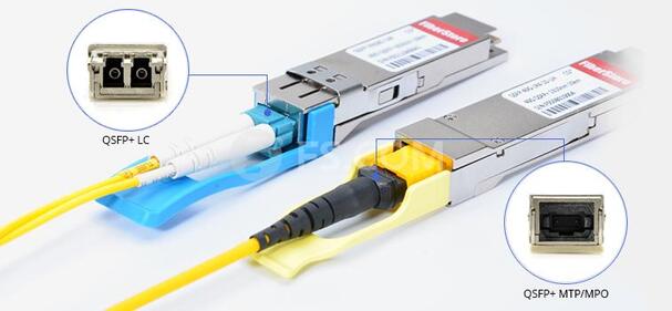
From the following figure, we can see the examples of QSFP+ modules with two different interfaces. The left one is the module with with LC interface, while the right one is with MTP/MPO interface. The differences between these two kinds of modules vary from the fiber types they work with to the working principles, which will be analyzed in the following text.
Different Fiber Types
As for the QSFP+ module designed with LC interface, it usually works with single mode fiber (SMF). Since SMF is able to support 40G network for a very long distance, the LC interface module is widely applied in long transmission. However, the QSFP+ module with MTP/MPO interface design is strongly recommended in the short distance application where the 40G signals are transmitted through multimode fiber (MMF). What should be paid attention to are some special QSFP+ modules, like QSFP-40G-PLRL4 and QSFP-40G-PLR4 module, which don’t fit the rule. Although the two kinds of modules mentioned above are designed with MTP/MPO interfaces, they are also capable of supporting 40G long distance transmission through SMF.
Different Working Principles
As shown in the following figure, QSFP+ module with LC interface has a very complicated working principle for transmitting 40G signals. At the beginning of the transmission, four 10G serial data signals via four channels are transmitted to laser drivers in the transmitting side. Then they are directly controlled by the laser drivers as four modulated lasers (DML) with different wavelengths. After that, the output of four DMLs are optically multiplexed as a total 40G optical signal and transmitted through the LC connector and the SMF. While in its receiving side, the 40G optical signal is demultiplexed into four individual 10G signals with different wavelengths, then collected by the discrete photo diode, and finally amplified by the TIA and outputted as electric data.

As for QSFP+ module with MTP/MPO interface, its working principle is much easier than the previous one as it doesn’t require CWDM technology. In its working process, the transmitter firstly converts four 10G parallel electrical input signals into parallel optical signals by using the laser array. Then the four 10G parallel optical signals are directly transmitted through the MMF ribbon in a parallel mode. Finally, these parallel optical signals are transmitted through the photo detector array and converted into parallel electrical output signals in the receiving side. To better understand the working principle, here offers the figure of its detailed working process.

Besides, the mentioned above QSFP+ module with MTP/MPO interface, like QSFP-40G-PLRL4 and QSFP-40G-PLR4, also works in a parallel mode that features four independent transmitting and receiving channels to finish 10G operations, achieving a whole 40G connection. The only difference of the working principle is that the signals are transmitted and received through eight SMF ribbons, hence this kind of module can also achieve a long distance transmission.
Conclusion
From this article, we can easily find that QSFP+ module with LC interface is more commonly used for long distance application, while QSFP+ module with MTP/MPO interface is a cost effective solution for short distance application. Except that, there is still a great difference for applications between the two kinds of modules due to their different working principle. As QSFP+ module with LC interface uses CWDM technology to transmit signals with different wavelengths through a pair of single mode fibers, the 40G signals can’t be separated into four 10G signals and transmitted to 10G devices. However, QSFP+ module with MTP/MPO interface can be used in the 40G to 10G application by using an external 12-fiber parallel to 2-fiber duplex breakout cable.
votre commentaire


|
|
|
|