-
With the continuously growing demand for higher capacity and bandwidth, the deployment of 40G Ethernet network becomes much more necessary than ever before. As one of the key components to accomplish a whole 40G connection, QSFP+ transceiver, a compact, hot-pluggable module, is designed with four independent channels to transmit and receive 10G signals, supporting 4x10 Gbit/s data rates. This kind of module can be used both in 40G to 40G application where one QSFP+ transceiver will be connected to another QSFP+ transceiver and in 10G to 40G application where one QSFP+ transceiver will be connected to four SFP+ transceivers.
Do you also want to upgrade your system from 10G to 40G Ethernet network by using QSFP+ transceiver? The following will detailedly describe the step-by-step procedures for installing QSFP+ transceiver and attaching optical network cable to the transceiver, which will be helpful for you to achieve a fast, smooth and seamless 40G network deployment.
QSFP+ Transceiver Installation
Before installing QSFP+ transceiver, three tools should be prepared for the 40G migration. One is the wrist strap or other grounding device with the function of avoiding ESD (electro-static discharge) occurrence. Another is the antistatic mat or antistatic foam, capable of setting the transceiver on. The other is the equipment for fiber-optic end-face cleaning and inspection. All of these tools are indispensable for making a secure and smooth installation.
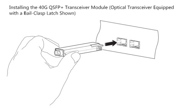
After that, you can start to install the QSFP+ transceiver according to the following procedures. Considering that there is either a pull-tab latch or a bail-clasp latch in QSFP+ transceiver, the procedures for both types will be listed below.
- Put the ESD wrist strap on and attach the other end of the ESD wrist strap to a properly grounded point on the chassis or the rack.
- Get the QSFP+ transceiver by removing its protective packaging.
- Check the QSFP+ transceiver label and confirm whether the type of the module is suitable for your network or not.
- Remove the optical bore dust plug from the transceiver and store it in a clean place, therefore it can be easily found and fast used next time.
- Since there are two kinds of latches for the transceivers, they should be connected to your network in different ways. As for the transceiver with a pull-tab latch, you should hold it to ensure the identifier label is on the top. As for another transceiver, you should keep its bail-clasp aligned in a vertical position (see the following figure).
- Then align and slide the transceiver to the module socket carefully until it contact with the socket electrical connector.
- Press firmly on the front of the QSFP+ transceiver with your thumb to fully seat the transceiver in the module socket.
- Reinstall the dust plug into the transceiver optical bore before attaching the optical network cable to the transceiver.
 Optical Network Cable Attachment
After installing the QSFP+ transceiver, you should attach the optical network cable to the transceiver to finish the whole 40G transmission. But how to attach the optical network cable? What should be paid attention to in the attaching procedures? The following will talk about this topic and give you answers.
Before making the 40G connection, you should ensure that the unplugged optical network cable connectors and the transceiver optical bore are protected by the dust plugs. Meanwhile, you should also check and clean the MPO connector or duplex LC connector end faces. Besides, you can only grasp the connector housing to plug or unplug the optical network cable. Once these points are confirmed, you can attach the optical network cable to your network.
The procedures for attaching the optical network cable to the transceiver are shown below.
- Remove the dust plugs from the optical network interface cable connectors and the QSFP+ transceiver module optical bores. Also, keep the dust plugs in a clean place.
- Check and clean the connector end faces of the optical network interface cable.
- Immediately attach the optical network interface cable connector to the QSFP+ transceiver.
- Pull slightly on the cable connector boot to check whether the optical network cable is fully seated. If not, please reattach it and make it seated.
Conclusion
From this paper, it can be easily learned to install the 40G QSFP+ transceivers and attach the optical network cables to the QSFP+ transceivers, hence the 40G connection can be smoothly finished in a correct way. Using the methods mentioned above to upgrading your network can protect the QSFP+ transceivers from being damaged and keep a stable performance for the 40G connection.
 votre commentaire
-
Nowadays, there is a widespread concern over the migration from traditional 10G to 40/100G Ethernet network, which seems to be an irreversible trend. As we know, 40/100G Ethernet network can greatly address the problem of very low network speed. Do you also consider upgrading your system for higher bandwidth and larger capacity? There is no doubt that fiber cables must be the first choice for a smooth 40/100G migration, which almost makes copper cables obsolete. But which kind of fiber should be chosen? Is there any key notice should be taken into consideration when selecting fiber for the migration? These problems will be explored and answered in the following parts.
Which Fiber Type Should Be Chosen for 40/100G Migration?
It is reported that over 80% of data centers support their network within 100 meters in recent years. That’s to say, if the fiber has the ability to transmit 40/100G signal for a short distance, it almost satisfies the needs for migration. In general, there are single mode and multimode fiber available for data centers, both of which are capable of supporting 40/100G data transmission links. But which one is the most cost effective for a whole 40/100G system? Let’s talk about it and seek the answer.
For single mode fiber, it can only carry a single light signal and has little modal dispersion in the transmission process, which is highly recommended for long distance transmission. While for multimode fiber, it is able to carry several light signals in the different modes that results in serious dispersion. What’s more, the longer the signals are transmitted, the larger the dispersion will be. Hence, multimode fiber is more popularly used in short distance transmission and much more inexpensive than single mode fiber.
In short, although single mode fiber has a higher performance in data transmission, multimode fiber is more suitable for 40/100G migration as the most cost effective fiber solution.
Notices for Data Transmission Distance
There are two kinds of multimode fiber patch cables, OM3 patch cable and OM4 patch cable that allow for smooth 40/100G migrations with different transmission distances. The following figure shows some commonly used transmission cases in 10G, 40G and 100G network, both of which are able to use short--wavelength (850 nanometer) transmission over OM3 and OM4 patch cable.
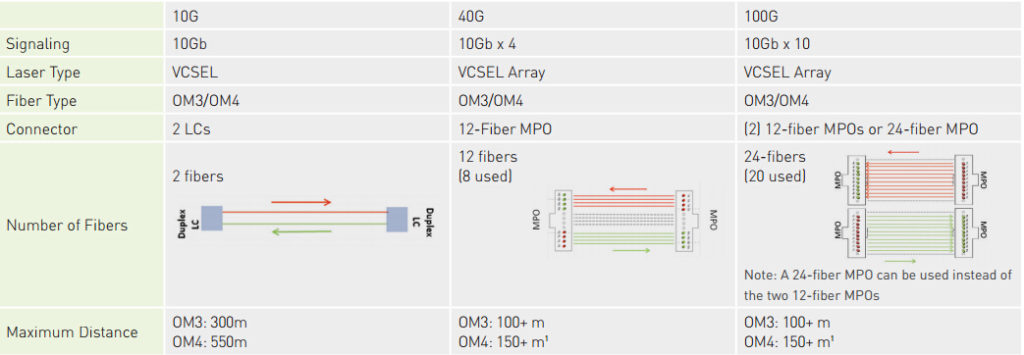
From the figure, we can easily learn that both OM3 and OM4 patch cable are suitable for 10G, 40G and 100G applications. As for OM3 patch cable, it is able to support 10G network at lengths up to 300 meters and 40/100G network at lengths up to 100 meters. Compared to OM3 patch cable, OM4 patch cable can transmit signals longer under the same network, which is also a little bit expensive. In fact, its transmission distance can be 550 meters in 10G network and 150 meters in 40/100G network.
Notices for Channel Insertion Loss
It is obvious that different cables have different channel insertion loss in 40/100G network, which may have different influences on the signal transmissions. Once the channel insertion loss is high, it may cause a failed or wrong signal transmission. So that, the channel insertion loss should be also noticed when selecting fibers.
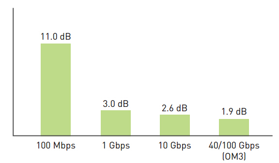
As shown in the following figure, the channel insertion loss by using OM3 patch cable is about 1.9 dB in supporting 40/100G data transmission link which is much lower than in supporting 10G link. If OM4 patch cable is selected to transmit 40/100G signals, the channel insertion loss is only 1.5dB. Undoubtedly, OM4 patch cable performs better than OM3 patch cable in this aspect.
Conclusion
Are you ready to make the 40/100G migration? If yes, you are suggested to choose multimode fiber as the most cost efficient fiber solution. According to the data transmission distance, you can choose OM3 patch cable to support 40/100G link at length up to 100 meters, which is more inexpensive than OM4 patch cable. If the distance can’t meet your requirement, you are suggest to choose OM4 patch cable with lower channel insertion loss.
votre commentaire
-
To face the challenge of migration from 10G to 40/100G Ethernet network, the fiber technology for higher data transmission speed has developed in a really fast manner. Under this trend, a series of high density fiber equipment, especially MPO/MTP products, are designed to control the costs, by way of maximizing return on assets. Have you ever known about MPO/MTP products, for instance, MPO/MTP cable, MPO/MTP cassette and MPO/MTP patch panel, which are very popularly used in recently years? Among these high density products, MPO/MTP cassette plays an indispensable role in 10G to 40/100G migration, as one of the ideal solutions for high density data centers. The following will mainly introduce the basic information of MPO/MTP cassette and illustrate how it is used for 10G network and the upgrading from 10G to 40/100G network.
MPO/MTP Cassette—Ideal Solution for High Density Fiber Cabling System
MPO/MTP cassette is a modular module that offers secure and smooth transition between MPO/MTP and LC or SC discrete connectors, achieving a better management on the high density fiber cabling system. It is always loaded with 12 or 24 fibers, with LC or SC adapters on the front side and MPO/MTP adapters at the rear, which enables user to take the fibers brought by a trunk cable and distribute them to duplex cable.
At present, there are two types of MPO/MTP cassettes available, LGX MPO/MTP cassette and HD MPO/MTP cassette, both of which have the advantage of scalability to increase density for optimum serviceability and manageability if the data center requires. Besides, there is a special kind of cassette designed with TAP port, which can be used to easily access and monitor the data.
Three Commonly Used MPO/MTP Cassettes
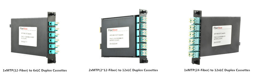
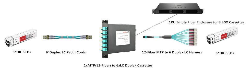
As we all know, the most widely used interface of 10G optics is LC connector. Accordingly, the commonly used MPO/MTP cassettes are MTP-LC cassettes that feature optimized performance and superior optical and mechanical properties. The following figure will show three MTP-LC cassettes, 1xMTP(12-Fiber) to 6xLC duplex cassette, 2xMTP(2*12-Fiber) to 12xLC duplex cassette and 1xMTP(24-Fiber) to 12xLC duplex cassette, with specific port configurations. Both of them can be used for 10G network and the application from 10G to 40/100G.
MPO/MTP Cassette for 10G to 10G Application
MPO/MTP cassette can be used for 10G network, with the function of connecting one 10G device to another one. It is generally known that a duplex LC fiber patch cable can be chosen for direct connection if the two 10G devices only need to be connected for a short distance transmission. However, once long distance transmission is required between the two devices, a MPO/MTP cassette would be a good choice for this 10G interconnection or cross connection. In the following figure, it gives an example of a 1xMTP(12-Fiber) to 6xLC duplex cassette used for 10G long distance transmission.
MPO/MTP Cassette for 10G to 40G Application
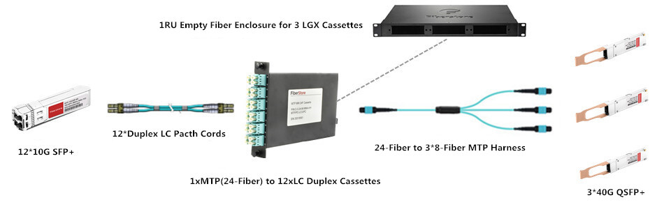
It is highly suggested to use a MPO/MTP cassette to connect 10G device to 40G device, as an optimal solution. Similarly, if the distance is very short between the 10G device and the 40G device, a MTP-4 duplex LC fiber patch cable can be used for direct connection. But when long distance connection is needed, this method can’t meet the requirement any more and a MPO/MTP cassette is strongly recommended for this interconnection or cross connection. The following figure also presents an example of 1xMTP(24-Fiber) to 12xLC duplex cassette for 10G to 40G connection.
MPO/MTP Cassette for 10G to 100G Application
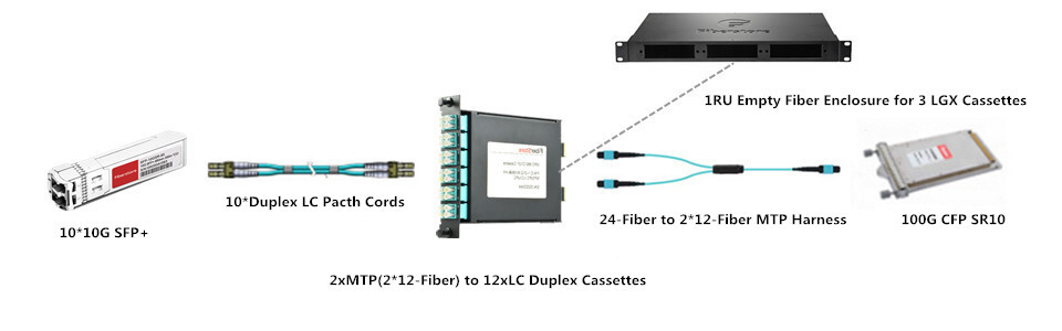
From the following figure, we can learn a 2xMTP(2*12-Fiber) to 12xLC duplex cassette is used for the 10G to 100G application. Is there any point we should note in the upgrading? Of course, a MTP-10 duplex LC fiber patch cable can simply address the upgrading for direct connection if the 10G device is not far from the 100G device. But when the distance between the devices is very long, the MPO/MTP cassette is also very essential for the 10G to 100G application.
Conclusion
MPO/MTP cassette enables fast deployment of high density data center infrastructure that also allows for improved troubleshooting and reconfiguration during moves, adds and changes. At present, there are three most commonly MPO/MTP cassettes, 1xMTP(12-Fiber) to 6xLC duplex cassette, 2xMTP(2*12-Fiber) to 12xLC duplex cassette and 1xMTP(24-Fiber) to 12xLC duplex cassette, both of which are able to support 10G network and the upgrading from 10G to 40/100G.
votre commentaire
-
It is well known that SFP+ transceivers like SFP-10G-SR and SFP-10G-SR-S are very commonly used and perform greatly in 10G short distance transmission. When higher bandwidth is required, several SFP+ transceivers can be used together to offer multiple 10G links as a common solution. However, if an individual 40G link is implemented in this case, it has the ability to perform higher with much faster data transmission rate than multiple 10G links. As the deployment of 40G Ethernet network is not so simple as that of 10G Ethernet network, the following will introduce three widely applied solutions for short distance transmission in 40G Ethernet network which can be useful for you to deploy individual 40G link instead of multiple 10G links.
Three Solutions to Support 40G Short Distance Transmission
With the popularity of 40G Ethernet network, 40G solutions, especially 40G QSFP+ modules, have been widely applied to finish 40G data transmission. At present, there are various kinds of 40G solutions available on the market, which are designed to support different applications. For 40G short distance application, three widely applied solutions, QSFP-40G-SR4, QSFP-40G-CSR4 and 40GBASE-CR4 QSFP+ direct attach copper cable will be introduced in details.
QSFP-40G-SR4 Module Solution
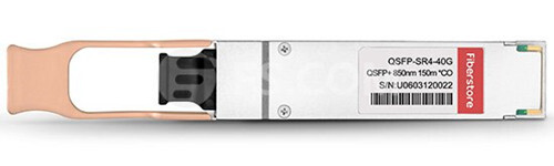
QSFP-40G-SR4 module is one of the most popular fiber optic transceiver for 40G short distances transmission, designed with 40GBase-SR4 standards. It is able to support high-bandwidth 40G signal transmission through 12-fiber parallel fiber, which is always terminated with MPO/MTP multi-fiber connectors. How long can it transmit 40G signals? If it works with OM3, it can support the 40G link at lengths up to 100 meters. If it transmit the 40G signals through OM4, the distance can be longer, 150 meters. In addition, QSFP-40G-SR4 module has the ability to connect four SFP-10G-SR modules by an 8-fiber MTP to 4 duplex LC cable. The following is an example of this module working with OM4 that you can find at FS.COM.
QSFP-40G-CSR4 Module Solution
As for QSFP-40G-CSR4 module, it is always referred to as an upgraded version of QSFP-40G-SR4 module that has a better performance to support 40G short distance transmission. Its working principle is similar to the previous one, which also works through 12-fiber parallel cables with MPO/MTP connectors to support 40G optical link. Besides, connection with four 10GBase-SR interfaces still can be done in a parallel 4x10G mode by using duplex fiber breakout cables. What higher performance does QSFP-40G-SR4 module have? In fact, it is reflected on the transmission distance which is extended to 300 meters through OM3 and 400 meters over OM4. Here offers an example of QSFP-40G-CSR4 module that works with OM3 for your reference.

40GBASE-CR4 QSFP+ Direct Attach Cable (DAC) Solution
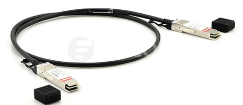
40GBASE-CR4 QSFP+ DAC can be also called 40GBASE-CR4 QSFP+ cable, which is very different from the first two 40G solutions. It is a pre-terminated copper cable with both ends terminated with QSFP+ modules. As for its working principle, it uses four lanes of twinaxial cable delivering serialized data at a rate of 10.3125 Gbit/s per lane to finish the 40G signal transmission.
Compared to the above-mentioned 40G modules, 40GBASE-CR4 QSFP+ DAC has a much lower manufacturing cost which is always not considered as a real optics, because of no expensive lasers or electronic components. At the same time, the transmission distance is also much shorter limited by the property of copper cable. In fact, it can only support the 40G signal transmission with a reach of 7 meters. Here also lists an example of 40GBASE-CR4 QSFP+ DAC for you to get a better understanding of the differences between this one and the above-mentioned modules.
Conclusion
If the 10G Ethernet network can not meet your demands any more, you are suggested to deploy 40G Ethernet network for much higher bandwidth and faster data transmission rate. As for the 40G solutions for short distance transmission, you can choose it according to the transmission distance your network requires. In general, 40GBASE-CR4 QSFP+ DAC would be a good choice to support your system within 7 meters with the lowest price, while QSFP-40G-SR4 module is much more suitable to be used in the application within 150 meters. As for QSFP-40G-CSR4 module, it is the most expensive but optimal solution that has the ability to support 40G signal transmission at lengths up to 400 meters.
votre commentaire
-
Since data centers have been experiencing an great infrastructure change to achieve higher levels of performance and scalability, the demand for 100G Ethernet network increases day by day. To better accommodate this great change, there are several kinds of transceivers designed for deploying 100G Ethernet network, such as, CFP, CFP2, CFP4, QSFP28, CPAK, etc. Among these 100G optics, QSFP28 transceiver offers the optimal solution for the 100G migration with the lowest power consumption which is very commonly used at present. In this paper, it will introduce QSFP28 transceiver and analyze the reason why QSFP28 transceiver is so popular in 100G Ethernet network.
QSFP28 Transceiver Overview
As the smallest 100G form factor transceiver, QSFP28 transceiver has the same size and lane number as 40G QSFP+ transceiver, which is implemented with four 25-Gbps lanes to achieve 100G transmission. With the design of an upgraded electrical interface, it is able to support signals rates up to 28 Gbit/s that makes the deployment of 100G Ethernet network as easy as that of 10G Ethernet networks.
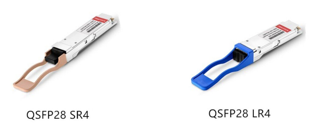
Generally, there are two types of QSFP28 transceivers, QSFP28 SR4 and QSFP28 LR4, which are used for different applications. As for QSFP28 SR4, it is suitable for 100G short distance transmission through multimode fiber up to 100 m. As for QSFP28 LR4, it is widely applied in 100G long distance transmission through single mode fiber, at lengths up to 10 km. The following figure shows the two types of QSFP28 transceivers for your reference.
What Can We Benefit From QSFP28 Transceiver?
There is no doubt that QSFP28 transceiver has a lot of advantages that make itself more popular than other 100G optics. In order to better deploy 100G Ethernet network, QSFP28 transceiver is designed with a strong improvement that increases port density and decreases power consumption with a lower cost, which will be illustrated detailedly in the following text.
Higher Port Density: As we know, the first generation of 100G transceiver is CFP, which is designed with a very large form factor. As for the next generations, CFP2 and CFP4, although their sizes decrease a lot, they are still larger than 40G QSFP+ transceiver. However, QSFP28 is published soon as the smallest 100G form factor transceiver with the same footprint and face plate density as QSFP+ transceiver. In general, with its advantage of high port density, we can install up to 36 QSFP28 on a 1RU switch on the front panel.
Lower Power Consumption: As for the general 100G optics, their power consumption ranges from 6 W to 24 W. In the contrast with these optics, QSFP28 transceiver transmits signals with the lowest power, less than 3.5 W. In short, QSFP28 transceiver is the most ideal solution for 100G transmission with the lowest power consumption at present.
Lower Cost: The deployment of 100G Ethernet network with QSFP28 transceiver can save a lot which mainly shows in the following aspects. Firstly, it can save considerable amount of money with the advantages of higher port density and lower power consumption. Secondly, it is implemented with four lanes, increasing the transmission capacity of every lane from 10G to 25G, thus it effectively decreases cost for each bit. Thirdly, both of its electrical and optical lanes work at the same speed that eliminates the costly gearbox found in CFP, CFP2 and CPAK. Finally, its way of migrating to 100G Ethernet network is also superior that can change from 10G-40G-100G to 10G-25G-100G or 10G-25G-50G-100G, much simplifying the cabling and saving the cost in data centers.
Conclusion
In short, QSFP28 transceiver will be more and more commonly used, ensuring data centers to scale 100G networks with the same simplicity as 10G networks. After knowing the advantages of QSFP28 transceiver, do you also want to achieve higher levels of performance and scalability by using QSFP28 transceiver for your system? If you only need a 100G short distance connection, you can choose QSFP28 SR4. And QSFP28 LR4 would be a good choice for 100G long distance transmission.
votre commentaire


|
|
|
|