-
As WDM revolution has already occurred with unanticipated swiftness, WDM technology is largely used in a really fast manner, dramatically promoting the network for high-volume data transmission over a single fiber cable. Have you ever wondered how does WDM technology work? What’s the difference between CWDM and DWDM technology? Which one is the most suitable for your network? To better understand CWDM and DWDM technology, this post will study the working principle of WDM technology and analyze the detailed difference between CWDM and DWDM technology.
The Working Principle of WDM Technology
Have you ever heard about the working principle of the prism? When a white light beam with different wavelengths pass through the prism, there should be a light dispersion. It will be changed into several light beams and leave the prism at different angles, just like a rainbow. To the contrary, if several light beams with different wavelengths pass through the prism, it will be changed into a white light beam. The following figure shows the details of how does the prism work.
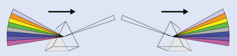
The working principle of WDM technology is similar to the above-mentioned principle. Without using additional fibers, WDM technology uses a multiplexer at the transmitter to combine multiple signals together, and a demultiplexer at the receiver to split them apart as shown in the following figure, so that multiple signals can be transmitted over a single fiber cable.

That’s to say, optical signals with different wavelengths are combined at the transmitter firstly, then will be transmitted together through the single optical fiber. Finally, the combined signals will be split into multiple signals with differing wavelengths again when arriving at the receiver. In the whole transmission process, each signal with its own wavelength will not interfere with each other. Therefore, the capacity of a fiber link can be expanded by simply putting the multiplexer and demultiplexer at each end.
The Differences Between CWDM and DWDM Technology
WDM technology is very efficient and largely used that enables the capacity of the network to be expanded without more fibers. In general, it can be divided into two types, CWDM (coarse wavelength division multiplexing) and DWDM (dense wavelength division multiplexing), both of which are indispensable technologies to increase capacity on the fiber links. However, there are many differences between the two types, which vary from wavelength spacing to transmission distance.
Wavelength Spacing
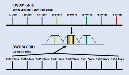
CWDM and DWDM are divided on the basis of different wavelength patterns, while the words “coarse” and “dense” reveal the difference in channel spacing. As for CWDM, it has the capability to carry up to 16 channels on a single fiber in the spectrum grid from 1270 nm to 1610 nm with a 20nm channel spacing. As for DWDM, it has a narrower channel spacing, 0.8 nm, which is able to transmit up to 160 channels from the wavelengths of 1525 nm to 1565 nm (C-band) or 1570 nm to 1610 nm (L-band). In comparison, the denser spacing and more channels allow DWDM to transmit more optical signals over the same fiber than CWDM. For the basic difference between CWDM and DWDM, you can take the following figure as reference.
Transmission Distance
CWDM and DWDM use the same working principle to multiplex different wavelengths of optical signal via a single fiber, but differ in applications for the ability to amplify the multiplexed signals. As CWDM has no ability to amplify the signals, it is always used in short distance transmission that can support the transmission at lengths up to 160 km. However, DWDM is designed for longer haul transmission, which can expand greater maximum capacity and transmit the signals longer. Thereby, CWDM is always the first choice for short distance applications, while DWDM could be the priority for long distance transmission.
Manufacturing Cost
Compared to DWDM, CWDM with uncooled laser uses electronic tuning that is easier to be manufactured with lower cost. Why? Because DWDM with cooled laser is more difficult to accommodate temperature tuning due to the non-uniform temperature distribution in a very wide wavelength, which results in high cost. Meanwhile, DWDM has a much narrower channel spacing which requires more sophisticated transceiver designs. Hence, the manufacturing cost of DWDM is much higher than of CWDM. Typically, a DWDM product is four or even five time more expensive than a CWDM counterpart.
Conclusion
With its advantage of high-volume data transmission over a single fiber cable, WDM technology becomes more and more commonly used and plays an important role in facing the increasing demands of today’s network. Along with the constant development and maturity of WDM technology, it is divided into CWDM and DWDM that are indispensable technologies with different features. You are suggested to choose the suitable one for your network according to their features, such as, transmission distance, channel numbers.
 1 commentaire
-
Nowadays, the demands for data transmission rate and data capacity become much higher than ever before, which makes 40G Ethernet network more and more prevalent. Under this inevitable trend, 40G Quad Small Form-factor Pluggable (QSFP+) transceiver is designed for 40G migration as the most economic and effective module. Do you have a good knowledge about 40G QSFP+ transceiver? Are you interested in upgrading your system into 40G Ethernet network? If yes, there is an important and basic problem you need to consider and deal with before the migration. Which kind of fiber patch cable is the most suitable and cost-efficient for connecting your 40G QSFP+ transceiver?
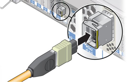
Importance of Fiber Patch Cable in 40G NetworkAs we all know, switches are need to be connected so as to form the whole 40G transmission network. How to connect these switches? As a basic component in the connection, fiber patch cable plays an indispensable role in connecting 40G QSFP+ transceivers which are plugged in Ethernet switches. Then the whole connection can be done, which is shown in the following figure for your reference.
Considering that the quality of the connection will largely affect the reliability and stability of the whole 40G network, the selection for fiber patch cable should be a priority in 40G migration. Since the connectivity of 40G is much more complex than ever, this article will provide the fiber patch cable selection guide as detailed as possible for connecting 40G QSFP+ transceivers.
Fiber Patch Cable Selection GuideChoosing the proper fiber patch cable becomes a big issue in 40G network not only because of the switch connections necessity, but also because of the transmission principle of the fiber optic signals and the high density trend of 40G transmission. To ensure the quality of the whole 40G network, two factors should be taken into consideration when selecting fiber patch cable, which are cable type and connector type.
Cable TypeAs the performances of optical signals are completely distinct over different fiber optic cables, selecting the most suitable cable type is essential. In principle, all the fiber optic cables can be used in 40G network. But if the data transmission rate increases, the optical signal transmission distance will get shorter. Hence, the longer the signal can be transmitted by fiber optic cable, the higher the performance of fiber optic cable will be.
As a result, OM3 patch cable and OM4 patch cable are suggested for connecting 40G QSFP+ transceivers in short distance, while the single mode fiber patch cable is the best choice for long transmission in 40G network. As for the two upgraded multimode cables, OM3 can support 40G network at lengths up to 100 meters and OM4 can support 40G network longer, up to 150 meters. Meanwhile, if you want to set up a long distance transmission in 40G network, you are suggest to choose single mode fiber patch cable that can transmit signals up to 10km.
Connector TypeThe selection of connector type of the fiber patch cable depends on the interface of 40G QSFP+ transceiver. At present, there are two interfaces commonly adopted by 40G QSFP+ transceiver which are MTP interface and LC interface. In short transmission application, 40G QSFP+ transceivers with MPO interface are usually used, thereby the patch cable with MTP connectors should be also selected. In long transmission application, 40G QSFP+ transceiver is always with LC interface, so that patch cable with duplex LC connector should be used.
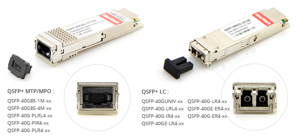
However, there are several 40G QSFP+ transceivers, for instance, 40GBASE-PLR4 and 40GBASE-PLRL4, which have MPO interfaces to support long transmission distance. If you choose these 40G QSFP+ transceivers for long distance transmission, the patch cables for connection should be also with MPO connectors.
ConclusionWhen selecting the right fiber patch cables for 40G QSFP+ transceivers, both cable type and connector type must be considered that are closely related to transmission distance, 40G network flexibility and reliability. Hope the selection guide for fiber patch cable in this paper is helpful for you to design your 40G Ethernet network.
votre commentaire
-
Introduction
With the fast development of the optical network, the demand for wider bandwidth and faster data transmission rates over farther distances are increasing day by day, which makes more and more fiber cables need to be installed when the optical network is designed. However, once the available fiber infrastructure is exhausted and can’t meet the increasing communication need any more, laying more fibers would become an impracticable or uneconomical method. Thereby, new capacity for the network needs to be created. In order to solve this, experts try to fall back on two new methods to expand the capacity of our network: increasing system bitrate to multiplex more signals and using WDM (wavelength division multiplexing) technology.
Comparison Between Increasing System Bitrate and Using WDM Technology
It is well known that both increasing system bitrate to multiplex more signals and using WDM technology can expand the capacity of our network. But the fact is that WDM technology is more commonly used for expanding the capacity of our network. What makes WDM technology so popular in optical network? What’s the advantage of WDM technology? The following will introduce the two methods of expanding the capacity of our network and seek the differences of the two methods.
- Increasing System Bitrate
Nowadays, most of our systems have already worked in 2.5 GB network. If we want to increase our system bitrate to multiplex more signals for expanding capacity, we should upgrade our system to 10 GB network. However, the upgrading process requires changing out all the electronics in our network which should be an expensive project. Taking the high upgrade cost into consideration, it is not recommended to expand capacity by increasing system bitrate to multiplex more signals. - Using WDM Technology
In contrast to upgrading our system, using WDM technology to expand the capacity of our network should be a quite advisable, cost-effective way that doesn’t require more fiber cables or changing out the electronics in our network. WDM technology takes great advantage of the enormous bandwidth of the optical fiber and makes bidirectional communications via one strand of fiber possible. To be brief, WDM technology creates virtual fibers to transmit data, which is the optimal method to expand capacity in optic network at present. As WDM technology is developed fast and tended to be mature, it is strongly advised to use this technology for promoting the network with high-volume data transmission over one single optical fiber.
More Things About WDM Technology You Should Know
The word of WDM stands for wavelength-division multiplexing. From its name, it is easy to know that the technology is using different wavelengths of light from a laser or a LED to multiplex two or more optical carrier signals over a single optical fiber. In its working process, without using additional fibers, optical carrier signals with different wavelengths are combined at the ingress, then transmitted together through the single optical fiber, and finally separated into individual signals with differing wavelengths at the express again as shown in the following figure.

At present, there are two types of WDM technology, CWDM (coarse wavelength division multiplexing) and DWDM (dense wavelength division multiplexing), both of which are indispensable and popular technologies to expand capacity on the fiber links. To some extent, WDM technology strongly multiplies the capacity of the network that plays an important role in meeting the increasing requirement of modern network.
Conclusion
The WDM revolution has already occurred with unexpected swiftness, which is more popular and commonly used for expanding the capacity than increasing system bitrate in today’s network. Although WDM technology is lack of a long history, the maturity of the technology have been realized WDM systems tailored specifically to the metropolitan area, providing high bandwidth and high capacity at a relatively low cost.
votre commentaire
- Increasing System Bitrate
-
Introduction
With the popularity of cloud computing and big data, the data throughput continually increases, which makes 40/100G Ethernet network more commonplace and now become a prevalent trend for data-center. In order to keep pace with the rapidly developing network, there are a series of MPO/MTP products designed for the reliable and quick operations in high-density data centers, such as, MTP/MPO trunk cable, MTP/MPO harness cable and MPO/MTP cassette. Have you ever wondered what do MPO/MTP stand for? What are the functions of these MPO/MTP products? In this article, it will give the explanation for MPO/MTP and some commonly used MPO/MTP products for your reference.
MPO/MTP Technology Overview
The word MPO is also referred to as “Multiple-Fiber Push-On/Pull-off”, while MTP is a upgrade version of the former MPO, with better optical and mechanical performance. As a high-density, high-performance solution for data centers, MPO/MTP technology is deployed for multi-fiber applications by pulling just one single cable with multiple fibers. Through this technology, you can replace 12 or 24 LC connectors with only one MPO/MTP connector. Generally, MPO/MTP technology is widely used for 40/100G Ethernet network as well as fast installation of enterprise data centers nowadays.
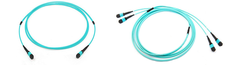
MPO/MTP Patch Cable
MPO/MTP patch cable is composed of MPO/MTP cable and MPO/MTP connectors, which is commonly used when 40G or 100G active transceivers (e.g., QSFP+ and QSFP28 transceivers) are employed with MTP/MPO interface. For its special internal structure of multi-fiber, MPO/MTP patch cable has a great improvement in performance, for example, less space, scalability, thereby significant space and cost savings are provided to user. As for MTP/MPO connector, it has many fiber optic channels to transmit signals, which becomes the up-and-coming standard optical interface for 40/100G Ethernet network.
Generally, there are two commonly used MPO/MTP patch cables, MTP/MPO trunk cable and MTP/MPO harness cable, which occupy the most part of high density multi-fiber cables market.
MTP/MPO Trunk Cable
MTP/MPO trunk cable is available with 12, 24, 48 and 72 fibers. For instance, a 72-fiber trunk cable can be terminated with 6 MPO/MTP connectors. It usually serves as a permanent link connecting MPO/MTP modules to each other, which is a great solution to reduce the time cost with easy installation and eliminate termination errors. Another advantage is to take up less space, which is very convenient to use. In short, it plays an important role in the data centers with high density requirement and may be the best choice for permanent connection.
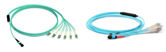
 MTP/MPO Harness Cable
MTP/MPO harness cable is designed for the transition from multi-fiber cables to single fiber cables or between the duplex connectors, which provides a reliable, cost-effective cabling system for migrating from legacy 10G to higher speed 40G/100G Ethernet. With the property of flexible connections, MTP/MPO harness cable is indispensable for high-density data centers.
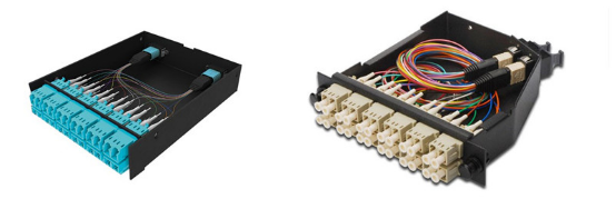
MPO/MTP Cassette
MPO cassette modules are usually fitted with 12 or 24 fibers, with LC, SC or E2000 adapters on the front side and MPO/MTP adapters at the rear. As a high density module, it can distribute the fibers brought by a trunk cable to a duplex cable that serves the transition from ribbon cables terminated with MPO/MTP connector to more common LC or SC interface used on the transceiver terminal equipment.
Conclusion
Compared with traditional fiber products, there are many improvements in MPO/MTP Products, such as, faster and easier installation, lower cost and higher density with less space. There is no doubt that more and more MPO/MTP products will be developed to meet the increasingly high demand of data centers, which will eventually flood the high-density data center.
votre commentaire
-
To meet the requirement of the fiber market, fiber optic patch cables have become more and more diverse which can be used for different applications. When choosing fiber optic patch cables, you might hear descriptions like SC to ST patch cable, LC to SC patch cable, LC to LC single mode fiber patch cable. Have you ever wondered what do LC, SC, ST stand for? Is there any difference between these types? In fact, these words refer to the different types of fiber optic connectors that are distinct from each other. The following will give the explanations for some commonly used fiber optic connectors, so that you can pick the right fiber optic connector for the sake of correct use.
Fiber Optic Connector Overview
The fiber optic connector is the device terminating the end of a fiber optic cable, which can be engaged and disengaged. In detail, it can connect the fiber optic equipment rigorously and conveniently without splicing, which is designed for maximally sending the light signal from optical transmitter to the receiver and minimizing the bad impact caused by the transmission. With the fast development of optical network, there are about 100 fiber optic connectors developed to meet the market needs, for instance, LC connector, SC connector, FC connector and ST connector which are largely used in different applications.
Different fiber optic connectors vary from the size to the application method. Here are the detail information about the four commonly used connectors for your reference.
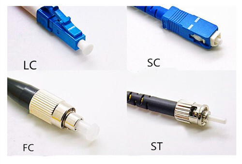
LC Fiber Optic Connector
LC fiber optic connector can be called Lucent Connector, Little Connector or Local Connector. It was invented by Bell, which makes a significant breakthrough for high density telecommunication. The coupling type of LC fiber optic connector is snap and its ferrule diameter is 1.25 mm. For its RJ-style latch clip design, it is very easy to operate. The size of LC connector is smaller than SC connector’s, which attends to improve the density of optical fiber connector. As for its application, it is always used in High-density connections, SFP and SFP+ transceivers, XFP transceivers. Along with the development of LC compatible transceivers and active networking components, it will keep growth in the FTTH area.
SC Fiber Optic Connector
SC fiber optic connector is rectangular and bigger than LC connector, which was developed by Nippon Telegraph and Telephone (NNT) in Japan. It can also be called Subscriber Connector, Square Connector or Standard Connector. Its ferrule diameter is 2.5 mm, twice as long as LC fiber optic connector’s. As for its application, it is very convenient to plug and pull without any revolve. With the property of high temperature resistance and oxidation resistance, it is usually connected to the lateral interface of the transmission equipment. Compared with other connectors, it is not very expensive and works easily and fast, which would be a good choice for most applications, such as, Datacom and telecom, GPON, EPON and GBIC.
FC Fiber Optic Connector
FC fiber optic connector is round and threaded that is also referred to as Ferrule Connector. It was also developed by NNT, with the purpose of being applied for single-mode optic fiber and polarization-maintaining optic fiber. Furthermore, it was the first fiber optic connector with a ceramic ferrule and the ferrule diameter is 2.5mm, as long as of SC fiber optic connector. However, FC connector is becoming less common and mostly replaced by SC and LC connector for its vibration loosening and insertion loss.
ST Fiber Optic Connector
ST fiber optic connector was designed by AT&T shortly after the arrival of the FC connector. The word ST refers to Straight Tip. It is probably still the most popular connector for multimode networks, like most buildings and campuses, which has a bayonet mount and a long cylindrical 2.5 mm ceramic (usually) or polymer ferrule to hold the fiber. For its spring-loaded structure, you’d better to check whether it is seated properly before use. If there is still high loss, you can try to reconnect it to see if it makes a difference.
Conclusion
It’s clear that all of the connectors mentioned in this paper have a place in the market. Except these connectors, there are many other popular types, such as, MPO connector, MU connector and MT-RJ connector. These types of connectors are distinct from each other, designed for different applications. Hence, you should select the right connector for your network, so that there will be no connection problems when installing the complicated fiber equipment.
votre commentaire


|
|
|
|